Table of Contents >> Show >> Hide
- What Is FiberGrid?
- How FiberGrid Works
- Why FiberGrid Matters
- The Main Benefits of FiberGrid
- Real-World Examples and Use Cases
- FiberGrid and the Bigger Optical Sensor Trend
- Design Considerations Before Building
- Limitations of FiberGrid
- How FiberGrid Compares With Traditional Sensors
- Why Makers Should Pay Attention
- Practical Experiences and Lessons From Working With FiberGrid-Style Optical Sensing
- Conclusion
FiberGrid is one of those delightfully clever engineering ideas that makes you stop, blink twice, and say, “Wait… why are we making this so complicated?” Instead of filling a robot, custom controller, interactive art piece, or homebrew machine with dozens of switches, analog inputs, tiny circuit boards, signal conditioners, and wiring headaches, FiberGrid turns the humble plastic optical fiber into a low-cost sensing network. The concept is simple but powerful: send light through plastic fibers, let 3D-printed mechanical parts block some of that light, and use a camera plus software to read the brightness changes as sensor values.
In other words, FiberGrid does not try to make every sensor smarter. It makes the whole sensing system simpler. That is a refreshing twist in a world where even a toaster can now demand a firmware update before breakfast.
At its heart, FiberGrid is an inexpensive optical sensor framework for robotics and maker projects. It is open, experimental, and aimed at builders who want to create many sensors without buying a mountain of microcontrollers or studying analog electronics until their coffee turns cold. For educators, hobbyists, robotics clubs, DIY inventors, and rapid prototyping teams, FiberGrid offers an appealing idea: use light, plastic fiber, 3D printing, and computer vision to collect sensor data at scale.
What Is FiberGrid?
FiberGrid is a 3D-printed optical sensing framework designed to read many mechanical sensors through a centralized camera system. The project uses inexpensive plastic optical fiber, a light source, a camera enclosure, and software that turns brightness levels into usable sensor readings. Rather than wiring each sensor to a separate electronic input, the system routes light through fibers and observes the fiber ends as a visual grid.
The key phrase is light blocking. A FiberGrid sensor can be designed so that movement, pressure, rotation, bending, pressing, or sliding blocks part of a light path. The more light that is blocked, the lower the brightness detected at the camera end. Software then converts that brightness into a numerical value. That means FiberGrid can provide analog-style readings, not just simple on/off states.
This makes FiberGrid especially interesting for robotics. Robots are greedy little creatures when it comes to sensors. A simple robot may begin with two limit switches and a dream. Then it needs wheel encoders, bump sensors, finger pressure, joystick control, gripper feedback, position detection, and suddenly the wiring harness looks like spaghetti attending a robotics conference. FiberGrid proposes a different route: move the sensing burden into optics and computer vision.
How FiberGrid Works
1. Light Starts at the Source
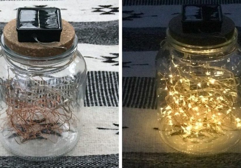
The hardware begins with a light source, such as an LED lamp or flashlight. Light is directed toward a grid of exposed plastic fiber ends. These fibers act as tiny light pipes. Plastic optical fiber is flexible, cheap, easy to cut, and forgiving compared with more delicate glass fiber systems.
2. Fibers Carry Light to Mechanical Sensors
Each fiber routes light to a sensor location. A 3D-printed part, such as a lever, button, wheel, gate, or spring-loaded mechanism, changes how much light reaches the return fiber. For example, pressing a button may lower a plastic tab that partially blocks the light beam. Turning a wheel may move slots past a fiber pair, creating pulses. Tilting a joystick may dim different corners of a fiber arrangement.
3. Return Fibers Bring Light Back to the Camera
After passing through the sensor, the remaining light travels through another fiber back to the camera module. The exposed ends of many fibers are arranged in a grid, like tiny glowing pixels waiting to be interpreted.
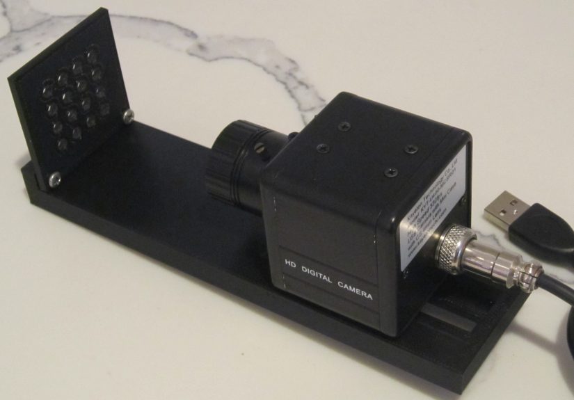
4. A Camera Reads the Grid
A camera watches the fiber-end grid. The software knows where each fiber appears in the image. It measures brightness in each region and converts that measurement into a sensor value. When the mechanical sensor blocks more light, the brightness drops. When the light path opens, the brightness rises.
5. Software Turns Brightness Into Data
The FiberGrid software approach separates calibration from everyday reading. A calibration utility identifies the fiber locations in the camera image. Once those positions are known, the driver can read brightness values repeatedly. This is where computer vision does the heavy lifting. Instead of reading voltages from pins, the program reads pixels from a camera frame.
That design choice is what makes FiberGrid feel so playful. It treats a camera as a multi-channel optical input board. The camera does not know it is reading robot sensors. It just sees dots of light. The software gives those dots meaning.
Why FiberGrid Matters
FiberGrid is not trying to replace every sensor technology. It will not magically outperform precision industrial encoders, high-end force sensors, fiber Bragg grating systems, or laboratory-grade optical instruments. But it does something very useful: it lowers the barrier to building lots of sensors quickly.
Traditional robotics projects often run into three practical problems: cost, wiring complexity, and input limitations. Every new analog sensor may require a microcontroller pin, an ADC channel, filtering, pull-up or pull-down resistors, debouncing, shielding, calibration, and code. One or two sensors are easy. Fifty sensors can become a tiny electrical jungle.
FiberGrid attacks that problem by centralizing the sensing interface. With one camera, one light source, plastic fibers, and printed mechanisms, a builder can experiment with many sensor points. For educational settings, this is a big deal. Students can learn mechanical design, sensing principles, computer vision, calibration, and robotics feedback without having to wire a custom circuit for every input.
The Main Benefits of FiberGrid
Low Cost
The most obvious benefit is price. Plastic optical fiber, LEDs, basic USB cameras, and 3D-printed parts are accessible to hobbyists and schools. The project’s original materials describe using inexpensive end-glow plastic fiber, consumer cameras, LED lighting, and black PLA to reduce ambient light. That is a wonderfully maker-friendly shopping list. No rare unicorn chips required.
Scalability
A major appeal of FiberGrid is the possibility of reading many sensors with one camera. The prototype concept discusses hundreds of analog-style sensing points. That does not mean every build will achieve perfect performance at that scale, but the architecture is clearly designed around multiplexing. The camera image becomes the sensor array.
Electrical Simplicity
Because the sensing action is optical and mechanical, many common electronics headaches are reduced. Builders do not need to create a separate electrical circuit at each sensing point. There is less concern about switch bounce, long analog wires, induced noise, reference voltages, or limited microcontroller input pins. The result is not “no complexity,” but it moves the complexity into mechanical design, optics, calibration, and image processing.
Good for Rapid Prototyping
FiberGrid is especially appealing when the goal is to test an idea quickly. Want a custom joystick? Print a mechanism, route fibers, and watch brightness changes. Want a simple optical encoder? Use a slotted wheel and two fibers. Want a pressure-sensitive button? Print a part that gradually blocks light as it moves. The framework invites experimentation.
Flexible Sensor Design
The same basic principle can support many sensor shapes. A light gate can detect position. A rotating disk can become an encoder. A sliding shutter can create a linear sensor. A spring-loaded button can become an analog input. A flexible printed structure can dim light under pressure. FiberGrid’s biggest strength is not one perfect sensor; it is the ability to create many imperfect-but-useful sensors cheaply.
Real-World Examples and Use Cases
Robotics Feedback
Robots need feedback to act intelligently. A gripper that cannot sense contact is just a tiny mechanical claw with confidence issues. FiberGrid can be used to explore contact sensing, position feedback, wheel rotation, joint limits, or soft-touch inputs. For small robots and classroom projects, this can make feedback more approachable.
3D-Printed Joysticks
One FiberGrid demonstration uses a 3D-printed analog joystick. The design uses an LED and fibers positioned around a small printed mechanism. When the joystick is pressed or tilted, it blocks different amounts of light. The camera reads the resulting brightness changes. It is not meant to compete with a commercial game controller, but it beautifully demonstrates the idea: mechanical motion becomes light variation, and light variation becomes data.
Optical Encoders
FiberGrid is also well suited for optical encoders. A rotating wheel with slots or patterned edges can interrupt light between fibers. By reading the changing light levels, software can estimate rotation. With careful design, multiple tracks could improve direction detection or resolution. This is the kind of application where optical sensing already makes intuitive sense.
STEM Education
FiberGrid has strong educational potential. Students can see the relationship between physical motion and sensor data directly. They can print parts, cut fiber, adjust lighting, calibrate a camera, and write code that reads brightness. That combines physics, design, programming, robotics, and troubleshooting in one hands-on package. It is also more exciting than telling students, “Today we will discuss ADC channels,” which is a reliable way to make half the room discover sudden interest in the ceiling tiles.
Interactive Art and Installations
Artists and designers often need unusual input systems: floor pads, touch panels, kinetic sculptures, musical interfaces, arcade controls, or museum exhibits. FiberGrid can support custom input layouts without placing electronics at every interaction point. Light and fiber can travel through structures where conventional wiring may be awkward.
Assistive Devices and Custom Controllers
Because the framework encourages custom shapes, it may be useful for experimental assistive input devices. A controller can be designed around a user’s movement range rather than forcing the user to adapt to a standard device. Any serious assistive or safety-critical application would need careful validation, but as a prototyping method, FiberGrid opens interesting doors.
FiberGrid and the Bigger Optical Sensor Trend
FiberGrid fits into a broader movement toward optical sensing in robotics, healthcare, structural monitoring, and wearable technology. Optical fiber sensors can be lightweight, electrically isolated, resistant to electromagnetic interference, and suitable for environments where conventional electronics may struggle. High-end systems use advanced techniques such as fiber Bragg gratings, interferometry, spectroscopy, or distributed sensing. FiberGrid is more humble. It focuses on intensity: how bright is the light coming through this fiber?
That simplicity is both its advantage and its limitation. Intensity-based sensing can be inexpensive and easy to understand, but it can be affected by lighting stability, fiber cuts, camera exposure, ambient light, mechanical alignment, dust, and aging components. Still, for many maker projects, “good enough and affordable” beats “perfect but financially rude.”
Recent work in vision-based tactile sensors also shows why camera-based sensing is attractive. Cameras are cheap, high resolution, and easy to integrate with modern software. The challenge is often packaging, calibration, and interpretation. FiberGrid approaches this from a maker angle: keep the camera centralized and let fibers carry optical information from many places back to the image sensor.
Design Considerations Before Building
Ambient Light Control
FiberGrid depends on brightness readings, so unwanted light is the enemy. Black PLA, enclosed camera housings, covered fibers, and consistent illumination help reduce noise. A bright room, sunlight, or reflective printed parts can confuse readings. The system likes drama-free lighting. Think “calm laboratory,” not “robotics project under a disco ball.”
Camera Frame Rate
The camera’s frame rate limits how fast the system can read changes. A basic USB camera may be fine for buttons, slow mechanisms, or educational demonstrations. Faster robotics feedback may require a higher-frame-rate camera. Resolution matters, but not always as much as frame rate and focus. The camera mainly needs to distinguish fiber ends clearly and repeatedly.
Clean Fiber Cuts
Plastic fiber ends should be cut cleanly. Rough cuts scatter light unpredictably and reduce signal quality. Builders may need to experiment with cutting tools, polishing methods, and connector designs. In low-cost optical systems, tiny mechanical details can have surprisingly large effects.
Calibration
Calibration is not optional. The software must know where each fiber appears in the camera image and what brightness range represents normal operation. A well-built device should keep fiber positions stable, allowing calibration to be reused. But if fibers move, the camera shifts, or the enclosure flexes, readings may drift.
Mechanical Repeatability
The best FiberGrid sensors will be mechanically consistent. A button should return to the same position. A shutter should block light predictably. A joystick should not grind, wobble, or accidentally block every fiber like an overenthusiastic curtain. Good 3D printing, sensible tolerances, and simple mechanisms matter.
Limitations of FiberGrid
No framework is magic, and FiberGrid is no exception. It is inexpensive and clever, but it has trade-offs. Sample rate depends on the camera and processing pipeline. The hardware can be bulkier than tiny electronic sensors. The system is sensitive to alignment and lighting. Intensity readings may drift if the light source changes or the fibers shift. A high-quality commercial sensor will often be more accurate, more compact, and more reliable.
FiberGrid should be viewed as a prototyping and educational framework, not a drop-in replacement for certified industrial sensors. It is excellent for experimentation, custom input devices, robotics learning, and situations where many low-cost sensing points are more valuable than laboratory precision.
How FiberGrid Compares With Traditional Sensors
Traditional electronic sensors usually measure voltage, resistance, capacitance, magnetic fields, or digital pulses. They are often compact and reliable, but scaling them can require more wiring and interface electronics. FiberGrid uses optical paths instead. The sensor itself can be a simple printed object that changes light transmission.
Compared with a standard limit switch, FiberGrid may be more complex at first because it needs fiber routing and camera calibration. Compared with dozens of limit switches, however, it can become attractive because the camera reads many channels at once. Compared with a potentiometer, a FiberGrid analog mechanism may be less precise, but it can be cheaper and easier to customize. Compared with high-end optical fiber sensors, FiberGrid is far less sophisticated, but also far more accessible.
Why Makers Should Pay Attention
The most exciting thing about FiberGrid is not that it solves every sensing problem. It is that it changes how makers think about sensors. Instead of asking, “Which sensor module should I buy?” FiberGrid encourages the question, “Can I design a shape that changes light in a useful way?” That shift is powerful.
It encourages mechanical creativity. It also makes sensing visible. You can literally see the glowing fiber ends. You can press a mechanism and watch a dot dim. That kind of immediate feedback is great for learning and debugging. When something goes wrong, you are not only staring at a mysterious voltage reading; you can inspect the light path, the printed part, the fiber cut, the camera focus, and the brightness map.
Practical Experiences and Lessons From Working With FiberGrid-Style Optical Sensing
Anyone experimenting with a FiberGrid-style optical sensor framework quickly learns that the idea is beautifully simple, while the build process is full of tiny details that matter. The first practical lesson is that plastic optical fiber is friendly, but not magical. It bends, routes, and cuts more easily than glass fiber, but every bend radius, cut end, connector fit, and alignment choice can affect brightness. A sensor that works perfectly on the desk may act moody after being moved, bumped, or reassembled. This is not a failure; it is the normal personality of a low-cost optical prototype.
The second lesson is that black plastic is your friend. When building parts for light-based sensing, bright or translucent materials can create confusing reflections. Black PLA or another opaque dark material helps block stray light and makes readings more stable. Even then, enclosure design matters. A small gap near the camera, a shiny screw head, or a fiber end aimed at the wrong angle can create unexpected noise. In FiberGrid projects, the “boring” enclosure often does more work than the glamorous sensor mechanism.
The third lesson is that cameras are both wonderful and stubborn. A cheap USB camera can turn into a surprisingly capable multi-channel sensor reader, but autofocus, auto-exposure, and automatic white balance can cause trouble. If the camera keeps adjusting itself, the same sensor state may produce different brightness values. For best results, builders should lock exposure settings when possible, use steady lighting, and keep the camera focused at a fixed distance. Manual focus is a major advantage because the fiber grid does not need artistic blur. It needs reliable dots.
The fourth lesson is that calibration should be treated like part of the build, not an afterthought. A FiberGrid device becomes much more useful when the fiber positions are fixed, documented, and repeatable. Labeling fibers, saving calibration files, and testing each channel before assembling the final mechanism can prevent a long evening of “why is sensor seven pretending to be sensor twelve?” Good calibration turns a clever optical trick into a usable framework.
The fifth lesson is that the best sensors are mechanically simple. A printed shutter that moves smoothly across a light path is easier to tune than a complicated linkage with four springs, three sliding surfaces, and a grudge against geometry. When designing buttons, joysticks, or encoders, start with fewer moving parts. Add complexity only when the signal proves stable. The goal is not to impress the 3D printer; the goal is to get predictable light changes.
A sixth lesson is that FiberGrid is excellent for learning because mistakes are visible. If a button does not work, you can look at the camera feed. If one fiber is dim, you can inspect the cut. If two readings change together, maybe the light paths overlap or the mechanism blocks more than intended. This makes FiberGrid more approachable than many invisible electronic failures. Debugging becomes partly visual, partly mechanical, and partly software-based.
Finally, FiberGrid teaches a valuable engineering mindset: inexpensive does not mean careless. Low-cost systems require thoughtful design because they lack the expensive components that hide imperfections. A polished FiberGrid build depends on clean fabrication, good light control, stable calibration, and practical expectations. When those elements come together, the framework feels almost mischievous in the best way. It takes plastic fiber, a camera, and printed parts, then quietly says, “Congratulations, you now have a multi-sensor system.” That is the kind of engineering trick makers live for.
Conclusion
FiberGrid: An Inexpensive Optical Sensor Framework is a smart reminder that innovation does not always mean adding more electronics. Sometimes it means removing them. By using plastic optical fiber, 3D-printed parts, a light source, a camera, and computer vision, FiberGrid creates a flexible way to read many mechanical sensors without filling a project with individual electronic interfaces.
It is not perfect. It has limits in speed, compactness, precision, and environmental robustness. But for robotics education, maker prototyping, interactive devices, custom controllers, and low-cost experimentation, FiberGrid is wonderfully practical. It turns light into data, printed plastic into sensors, and a camera into a multi-input reader. That is not just clever. That is the kind of clever that makes a workbench feel like a laboratory and a pile of parts feel like possibility.